Deployment Model and Considerations
Deployment Models
Flink may be deployed as standalone servers, within Kubernetes and Flink Operator, YARN or as managed services.
As seen in the architecture chapter, the components to consider are Job manager and Task managers. But in production deployment other services are very important to address.

- Job Manager in application mode runs the cluster exclusively for one application. This is the recommended mode for resource isolation and load balancing.
- HA service: Flink's JobManager can be run in high availability mode which allows Flink to recover from JobManager faults. In order to failover faster, multiple standby JobManagers can be started to act as backups. Such service may be Zookeeper or Kubernetes job scheduler.
- Storage service for checkpoints management
- Resource service: kubernetes or Yarn for process scheduling and resource management
- Sink or source connectors for read/write operators: Kafka, Object Storage (S3), ElasticSearch,
In application mode, the user jars are bundled with the Flink distribution, and most likely packaged as a container image.
Apache Flink Standalone
The key points to work on: * The processes presented above are executed within the host operating system. * SREs have to restart failed processes, or allocation and de-allocation of resources during operation * For getting HA, Zookeeper needs to be started, and the Flink configuration needs to be changed to support multiple Job Managers. * Local directory is configured to store important information, like job state and metadata, to be used during recovery. Job identity helps to find persisted information.

See product chapter for the scripts to use.
Apache Flink within Kubernetes
For Kubernetes deployment, we should distinct three different mode of deployment:
- Standalone: the barebone deployment on kubernetes
- Native Kubernetes
- Flink Kubernetes Operator
Apache Flink has defined a Kubernetes Operator (FKO) to deploy and manage custom resources for Flink deployments.
Apache Flink Kubernetes Operator(FKO) acts as a control plane to manage the complete deployment lifecycle of Apache Flink applications.

The operator takes care of submitting, savepointing, upgrading and generally managing Flink jobs using the built-in Flink Kubernetes integration. The operator fully automates the entire lifecycle of the job manager, the task managers, and the applications. A FlinkDeployment is a manifest to define what needs to be deployed, and then the FKO manages the deployment by using Kubernetes deployments, pods... It supports query on the custom resources it manages.
Failures of Job Manager pod are handled by the Deployment Controller which takes care of spawning a new Job Manager.
As any Kubernetes operators, FKO can run namespace-scoped, to get multiple versions of the operator in the same Kubernetes cluster, or cluster-scoped for highly distributed deployment. The operator maps its custom resources to existing Kubernetes resources of deployments, replica sets, config maps, secrets, service accounts...
The following figure represents a simple deployment view of a Flink Cluster, in parallel of a Kafka cluster running on a Kubernetes platform:

The FKO may have two instances running in parallel. A Flink application may run on its own namespace and will be one job manager and n task managers. The Kafka cluster runs in its own namespace. PVC or File services are needed for Flink to persist checkpoints and savepoints.
Apache Flink Custom Resources
Once the Flink for Kubernetes Operator is running, we can submit jobs using FlinkDeployment (for Flink Application or for Job manager and task manager for session cluster) and FlinkSessionJob for Flink Session. The following figure represents those concepts:

On the left, a FlinkSessionJob references an existing FlinkDeployment as multiple session jobs can run into the same Flink cluster. The job declaration specifies the code to run with its specific configuration. While on the right, the application mode, has the job definition as part of the FlinkDeployment, as the JobManager and TaskManager mininum resource requirements.
The Apache Flink FlinkDeployment spec is here and is used to define Flink application (will have a job section) or session cluster (only job and task managers configuration).
The custom resource definition that describes the schema of a FlinkDeployment is a cluster wide resource. The Operator continuously tracks cluster events relating to the FlinkDeployment and FlinkSessionJob custom resources. The operator control flow is described in this note.. The important points to remember are:
- The operator control flow is: 1/ Observes the status of the currently deployed resource. 2/ Validates the new resource spec, 3/ Reconciles any required changes based on the new spec and the observed status.
- The Observer module assesses the current stateus of any deployed Flink resources.
- Observer is responsible for application upgrade.
- The job manager is validated via a call to its REST api and the status is recorded in the
jobManagerDeploymentStatus - A Job cannot be in running state without a healthy jobmanager.
A Flink Application is any user's program that spawns one or multiple Flink jobs from its main() method and is deploying a JobManager and n Task managers. They may run in their own namespace.
The Flink Kubernetes Operator is looking at different Flink Deployment, so it can be isolated within its own namespace.
Practices
When deploying the FKO it is important to specify the namespaces to watch for future deployments. The following command modify this list:
helm upgrade --install cp-flink-Kubernetes-operator --version "~1.130.0" confluentinc/flink-Kubernetes-operator --set watchNamespace="{flink, confluent, el-demo, rental}" -n flink
It is important to delete the operator pod and let Kubernetes restarts the FKO pod with the new config.
It is important to note that FlinkDeployment and FlinkApplication CRDs have a podTemplate, so ConfigMap(s) and Secret(s) can be used to configure environment variables for the Flink app. (Be sure to keep the container name as flink-main-container)
spec:
  podTemplate:
    spec:
      containers:
        - name: flink-main-container
          envFrom:
            - configMapRef:
                name: flink-app-cm
Confluent Cloud - Manager Services
Confluent Manager for Flink
The deployments for Confluent Platform and Confluent Manager for Flink, may look like in the following figure:

Confluent for Kubernetes Operator (CFK) is the control plane for deploying and managing Confluent in your Kubernetes private cloud environment. It defines custom resource definitions to support Kafka based resources like brokers, kraft controllers, topics, schema registry, connectors, cmfrestclass,...
Confluent Manager for Apache Flink® (CMF) is a Kubernetes operator, to manage Confluent Flink Applications, Environments, Compute pools, SQL Catalogs, we will detail those in a later section. CMF integrates with FKO to support Flink native custom resources.
The following figure illustrates the relationships between those kubernetes operators:

It is important to note that all Kubernetes Custom Resource deployments via kubectl go to the CFK with the apiVersion: platform.confluent.io/v1beta1. CRs touching Flink resources are delegated to the CMF operator. While deploying Flink components via the Confluent CLI or via REST API, the CMF CRDs use different apiVersion. Therefore it is possible to run CMF without CFK. Any CR with cmf.confluent.io/v1 as apiVersion needs to be created with confluent CLI, as using kubectl will not work because the CRDs are not known by Kubernetes.
Confluent Platform Console (also named C3) is integrated with CMF. CMF exposes a REST API and cli integration for managing Flink statements.
The following figure illustrates the current (Oct 2025) configuration of Flink solution deployment using the different CRs apiVersion.

-
Confluent FlinkEnvironments may be created with Manifests and uploaded via the Confluent CLI. Confluent Flink Environment differs from the Apache Flink Environment: it specifies which kubernetes namespace to use, which cmf REST class to connect to.
-
The metadata are persisted in an embedded database.
- The 'Environment' concept is to group multiple Flink applications together. This is an isolation layer for RBAC, and used to define Flink Configuration cross compute pools and applications deployed within an environment. Flink Configuration may include common observability and checkpointing storage (HDFS or S3) definitions. See one definition of FlinkEnvironment.
- a REST API supports all the external integration to the operator. Confluent Control Center and the
confluentcli are using this REST end point. - CMF manages FlinkDeployment resources internally
It is still possible to do pure OSS FlinkDeployment CRs but this strongly not recommended to leverage the full power of Confluent Platform and get Confluent Support.
Versioning
There is a Confluent version and interoperability document that should be updated at each release. But each time there is a new release you need to be sure to modify the references for:
- Confluent Platform (e.g. 8.1)
- Confluent Flink image (e.g. confluentinc/cp-flink-sql:1.19-cp4) in compute pool manifests
Confluent Flink Specific CRs
First an important document to read: The Confluent Operator API references.
Confluent Managed for Flink only manages Flink application mode and is using its own CRDs to define FlinkEnvironment and FlinkApplication. The CRDs are defined here. To be complete, it also define KafkaCatalog and ComputePool CRDs to defne SQL catalog, and other components introduced by Confluent Cloud.
- The new CRs for Environment, Application, Compute pool, and Flink Catalog:

- An FlinkEnvironment CRD define access control to flink resources and may define FlinkConfigurations cross applications. Environment level has precedence over Flink configuration for individual Flink applications. See one example in deployment/k8s/cmf.
apiVersion: platform.confluent.io/v1beta1
kind: FlinkEnvironment
metadata:
  name: dev-env
  namespace: confluent
spec:
  kubernetesNamespace: el-demo
  flinkApplicationDefaults:
    metadata:
      labels:
        env: dev-env
    spec:
      flinkConfiguration:
        taskmanager.numberOfTaskSlots: '1'
        state.backend.type: rocksdb
        state.checkpoints.dir: 's3a://flink/checkpoints'
        state.savepoints.dir: 's3a://flink/savepoints'
        state.backend.incremental: 'true'
        state.backend.rocksdb.use-bloom-filter: 'true'
        state.checkpoints.num-retained: '3'
        ...
      podTemplate:
        metadata:
          name: flink-pod-template
        spec:
          containers:
          - name: flink-main-container
            env:
            - name: S3_ENDPOINT
              valueFrom:
                secretKeyRef:
                  name: minio-s3-credentials
                  key: s3.endpoint
          ...
  cmfRestClassRef:
    name: default
    namespace: confluent
Some important elements to consider are:
-
kubernetesNamespaceis the namespace where the Flink deployment(s) will be deployed. So one environment establishes foundations for those Flink applications. It can define default Flink configuration for all applications and add common labels, like specifying the environment name they run in.FlinkApplicationis referencing back the Flink Environment which is not what Flink OSS Application does. The last piece is thecmfRestClassRefto reference the Kubernetes object/resource used to define access point to the CMF REST api. -
CMFRestClassdefines the client configuration to access CMF Rest APIs. This resource is referenced by other CMF resources (ex FlinkEnvironment, FlinkApplication) to access CMF Rest APIs. It alos supports security configuration, like the authentication mechanism and mTLS to access the REST api. -
FlinkApplication, in the context of Confluent Manager for Flink, is the same as Apache Flink but adds references to Environment and to the CMFRestClass. Every application runs on its own cluster, providing isolation between all applications. - Service Account: Service accounts provide a secure way for applications (like Flink jobs deployed via CMF) to interact with Confluent platform resources (e.g., Kafka clusters, Schema Registry) without relying on individual user credentials. Service accounts are central to the RBAC system. Need one service account per application or most likely per environment. The SA, cluster role, role and the role bindings need to be defined in the target namespace where the Flink app will be deployed. See this example for one application or the rental demo based on Table API app.
- KafkaCatalog is used to expose Kafka Topics as Tables for Flink. This CRD defines a Kafka Catalog object to connect to a Schema Registry. See catalog definition for the rental demo:
- Create a database to reference a Kafka cluster: See product documentation, one example of database definition
- ComputePools are used in the context of Flink SQL to execute SQL queries or statements. The ComputePool will only be used when the statement is deployed which happens after the compilation. It is a second level of Flink configuration for Flink cluster settings. See the kafka catalog example in external lookup demo. One important element is to specify the
imageattribute to referent a flink with SQL likeconfluentinc/cp-flink-sql:1.19-cp4. See docker hub for last tags available.
The configuration flexibility:
- FlinkConfiguration defined at the environment level can apply to all compute pools of this environment, and applications
- Compute pool configuration can apply to all SQL statements executed within the compute pool
- Flink Application has its own configuration, knowing that an application can be done with DataStream, or TableAPI.
Source of information
The examples in Confluent github provides scenario workflows to deploy and manage Confluent on Kubernetes including Flink and this article: How to Use Confluent for Kubernetes to Manage Resources Outside of Kubernetes covers part of the deployment.
High Availability
With Task managers running in parallel, if one fails the number of available slots drops, and the JobManager asks the Resource Manager to get new processing slots.

The application's restart strategy determines how often the JobManager restarts the application and how long it waits between restarts.
Flink OSS uses Zookeeper to manage multiple JobManagers and select the leader to control the execution of the streaming jobs.

Application's tasks checkpoints and other states are saved in a local and remote storages, but metadata are saved in Zookeeper. When a JobManager fails, all tasks that belong to its application are automatically cancelled. A new JobManager that takes over the work by getting information of the storage from Zookeeper, and then restarts the process with the JobManager.
Fault Tolerance
The central part of Flink’s fault tolerance mechanism is drawing consistent snapshots of the distributed data stream and operator state. The two major Flink features to support fault tolerance are the checkpoints and savepoints.
Checkpointing
Checkpoints are snapshots of the input data stream, capturing the state of each operator, of the DAG, at a specific point in time. They are created automatically and periodically by Flink. The saved states are used to recover from failures, and checkpoints are optimized for quick recovery.
Checkpoints allow maintaining consistency through exactly-once processing semantics, when the data stream source is able to support rewind to a defined recent point. When a failure occurs, Flink can restore the state of the operators and replay the records starting from the checkpoint.
In the event of a failure in a parallel execution, Flink halts the stream flow and restarts the operators from the most recent checkpoints. During data partition reallocation for processing, the associated states are also reallocated. States are stored in distributed file systems, and when Kafka is used as the data source, the committed read offsets are included in the checkpoint data.
Checkpointing is coordinated by the Job Manager, it knows the location of the latest completed checkpoint which will get important later on. This checkpointing and recovery mechanism can provide exactly-once consistency for application state, given that all operators checkpoint and restore all of their states and that all input streams are reset to the position up to which they were consumed when the checkpoint was taken. This will work perfectly with Kafka, but not with sockets or queues where messages are lost once consumed. Therefore exactly-once state consistency can be ensured only if all input streams are from reset-able data sources.
During the recovery and depending on the sink operators of an application, some result records might be emitted multiple times to downstream systems. Downstream systems need to be idempotent.
Flink utilizes the concept of Checkpoint Barriers to delineate records. These barriers separate records so that those received after the last snapshot are included in the next checkpoint, ensuring a clear and consistent state transition.
Barrier can be seen as a mark, a tag, in the data stream and aims to close a snapshot.
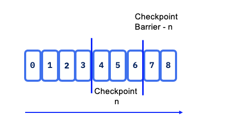
Checkpoint barriers flow with the stream, allowing them to be distributed across the system. When a sink operator — located at the end of a streaming Directed Acyclic Graph (DAG) — receives barrier n from all its input streams, it acknowledges snapshot n to the checkpoint coordinator.
Once all sink operators have acknowledged a snapshot, it is considered completed. After snapshot n is finalized, the job will not request any records from the source prior to that snapshot, ensuring data consistency and integrity.
State snapshots are stored in a state backend, which can include options such as in-memory storage, HDFS, object storage or RocksDB. This flexibility allows for optimal performance and scalability based on the application’s requirements.
When Flink triggers a checkpoint, it doesn't copy the whole database. It identifies which SST files are new since the last successful checkpoint. These new files are uploaded to durable storage (like S3 or HDFS). The checkpoint metadata simply "points" to these files.
With stateful distributed processing, scaling stateful operators, enforces state repartitioning and assigning to more or fewer parallel tasks. Keys are organized in key-groups, and key groups are assigned to tasks. Operators with operator list state are scaled by redistributing the list entries. Operators with operator union list state are scaled by broadcasting the full list of state entries to each task.
In the context of a KeyedStream, Flink functions as a key-value store where the key corresponds to the key in the stream. State updates do not require transactions, simplifying the update process.
For Batch processing there is no checkpoint, so in case of failure the stream is replayed from the beginning.
Savepoints
Savepoints are user triggered snapshot at a specific point in time. It is used during system operations like product upgrades. The Flink operator for kubernetes has custom resource definition to support the savepoint process. See also the end to end demo for savepoint in this folder.
Checkpoints impact throughput
- The persistence to remote storage is done asynchronously, but at the level of a task. So too frequent checkpointing will impact throughput. Now it also depends if the tasks are compute or IO intensive.
Interuption while writing checkpoints
- The processing will restart from the last persisted checkpoints so no data loss. Specially true when source of the data are coming from Kafka topics. The checkpoint points to last read-commited offset within topic/partition so Flink will reload from there
When Flink cluster has 10 nodes what happen in one node failure
It will depend of the operator allocation to the task to the task manager and what the operator needs (as state). At worse case the full DAG needs to be restored, every operator needs to rebuild their state so multiple task managers in the cluster.
It can take sometime to recover. Reread data and reprocess it, will take many seconds, or minutes.
With hot-hot deployment, it is possible to get the same running application running in parallel, and then switch the output sink / topic for the consumer. For real-time payment we can achieve around 3 to 7 seconds recovery time, with million of records per second.
Can we set one task manager one task to run all a DAG to make it simple?
It will depend of the application state size and logic to operate. If all state stays in memory, yes this is a common pattern to use. If state are bigger than physical memory of the computer running the task manager, then the processing needs more computers, so more task managers and need to distribute data. Then it needs distributed storage to persist states.
Eactly-once processing
When addressing exactly once processing, it is crucial to consider the following steps:
- Read Operation from the Source: Ensuring that the data is read exactly once is foundational. Flink's source connectors are designed to handle this reliably through mechanisms like checkpointing.
- Apply Processing Logic which involves operations such as window aggregation or other transformations, which can also be executed with exactly-once semantics when properly configured.
- Generate Results to a Sink introduces more complexity. While reading from the source and applying processing logic can be managed to ensure exactly-once semantics, generating a unique result to a sink depends on the target technology and its capabilities. Different sink technologies may have varying levels of support for exactly-once processing, requiring additional strategies such as idempotent writes or transactional sinks to achieve the desired consistency.
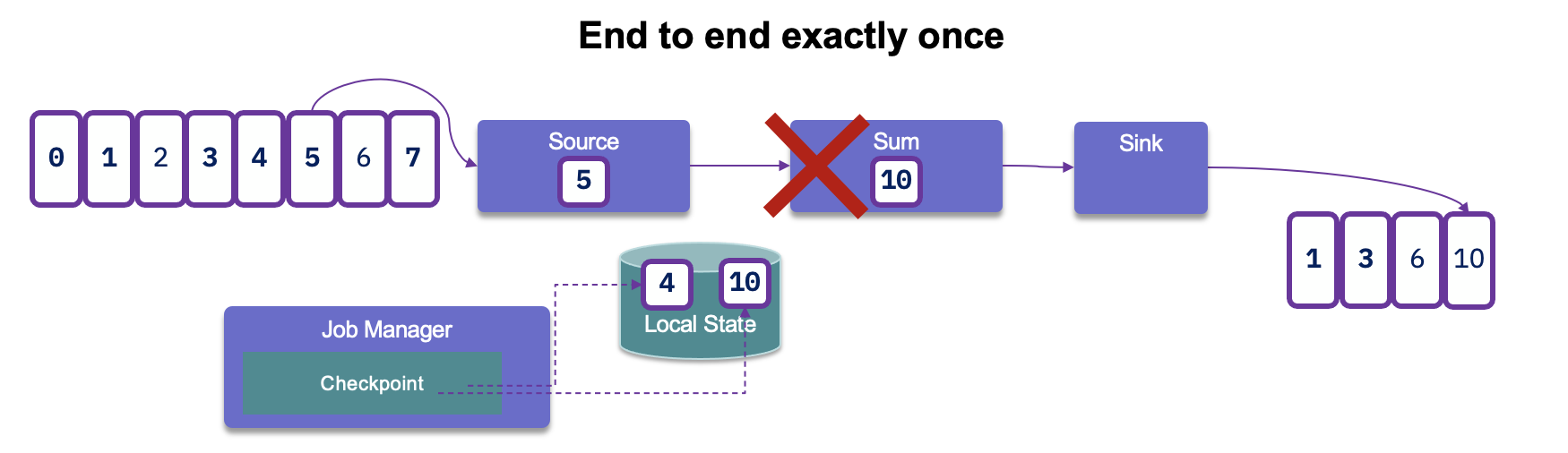
After reading records from Kafka, processing them, and generating results, if a failure occurs, Flink will revert to the last committed read offset. This means it will reload the records from Kafka and reprocess them. As a result, this can lead to duplicate entries being generated in the sink:
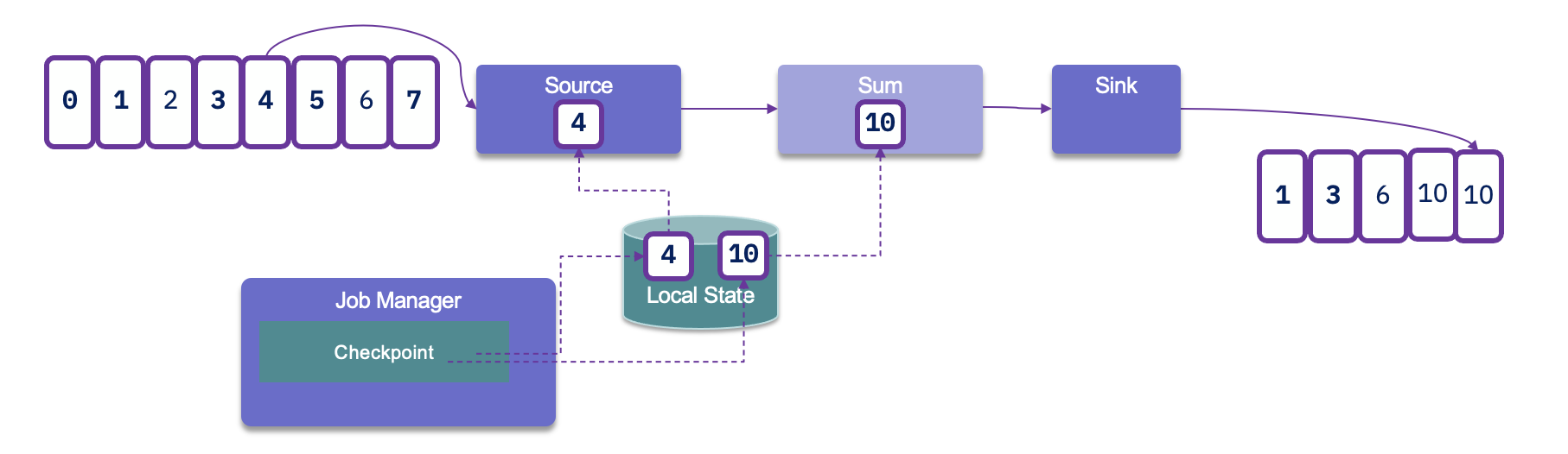
Since duplicates may occur, it is crucial to assess how downstream applications handle idempotence. Many distributed key-value stores are designed to provide consistent results even after retries, which can help manage duplicate entries effectively.
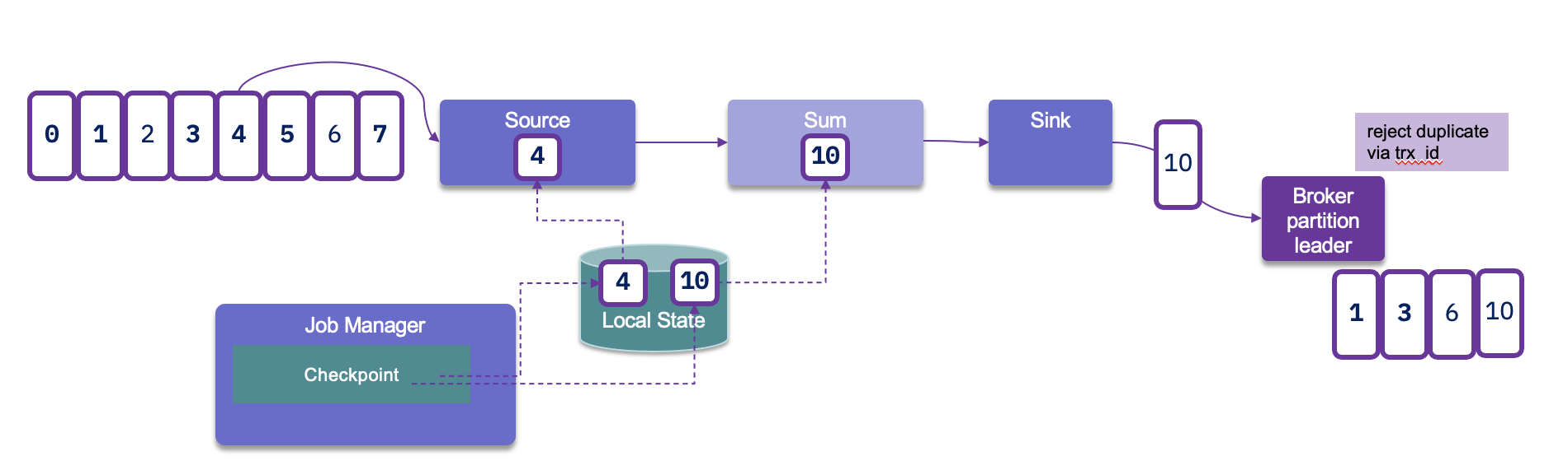
To achieve end-to-end exactly-once delivery, it is essential to utilize a sink that supports transactions and implements a two-phase commit protocol. In the event of a failure, this allows for the rollback of any output generated, ensuring that only successfully processed data is committed. However, it's important to note that implementing transactional outputs can impact overall latency.
Flink takes checkpoints periodically — typically every 10 seconds — which establishes the minimum latency we can expect at the sink level. This periodic checkpointing is a critical aspect of maintaining state consistency while balancing the need for timely data processing.
For Kafka Sink connector, as kafka producer, we need to set the transactionId, and the delivery guarantee type:
new KafkaSinkBuilder<String>()
    .setBootstrapServers(bootstrapURL)
    .setDeliverGuarantee(DeliveryGuarantee.EXACTLY_ONCE)
    .setTransactionalIdPrefix("store-sol")
With transaction ID, a sequence number is sent by the Kafka producer API to the broker, and so the partition leader will be able to remove duplicate retries.
When the checkpointing period is set, we need to also configure transaction.max.timeout.ms of the Kafka broker and transaction.timeout.ms for the producer (sink connector) to a higher timeout than the checkpointing interval plus the max expected Flink downtime. If not the Kafka broker will consider the connection has failed and will remove its state management.
Event-driven microservice
The evolution of microservice is to become more event-driven, which are stateful streaming applications that ingest event streams and process the events with application-specific business logic. This logic can be done in flow defined in Flink and executed in the clustered runtime.
State Backends and Storage
SLOs
- SLOs for latency, availability, recovery time.
- Definition of “critical job,” “non-critical job.”
- Naming conventions and tagging for jobs and clusters.