Cluster & Environment Management
Chapter updates
- Created 10/2025
- Updated 07/2027: DR works
1- Provisioning and Scaling Clusters
1.0 Sizing Flink Resources
Context
Sizing a Flink cluster is a complex project task, influenced by many factors, including workload demands, application logic, data characteristics, expected state size, required throughput and latency, concurrency, and hardware characteristics.
Because of those variables, every Flink deployment needs a unique sizing approach. The most effective method is to run a real job, on real hardware and tune Flink to that specific workload.
For architects seeking sizing guidance, it's helpful to consider:
- the workload semantic complexity, with the usage of aggregations, joins, windows, and processing type,
- the input throughput (MB/s or records/second),
- the expected Flink state size (GB): assess number of unique key with average size of data to keep
- the expected latency.
While Kafka sizing estimates are based on throughput and latency, this is a very crude method for Flink, as it overlooks many critical details.
For new Flink deployments, a preliminary estimate can be provided, but it's important to stress its inexact nature.
A simple Flink job can process approximately 10,000 records per second per CPU. However, a more substantial job, based on benchmarks, might process closer to 5,000 records per second per CPU.
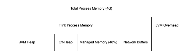
Flink Job and Task managers run in JVM, and the Task manager memory allocation looks like in the figure below. Flink memory is used by the Flink code, and is decomposed by 1/ network buffers to exchange partitions among operators, 2/ managed memory for state persistence buffering when using RockDB or ForSt, 3/ Task and Framework Off-heap, 4/ JVM Heap
-
Total Process Memory: Memory allocated to the JVM process.
-
For stateful streaming workloads, managed memory is usually the parameter that matters most. Shrink it and RocksDB gets less off-heap room for its block cache and other structures, so hot state falls back to disk more often and end-to-end latency increases. Grow it without proportionally sizing the JVM heap and the heap side for user functions can be squeezed, with GC events more likely to destabilize or fail the process.
-
In context of Confluent Platform for Flink, or Apache Flink, the deployment entity is an Application, which means 1 job manager and 1 to many task managers. So Kubernetes worker nodes host multiple job managers and Task managers. For most of the case the Job Manager use one core and 2GB of RAM. But when the number of keys in state grows it may be needed to go to 2-4 cores and 4-8 GB.
Preconditions / Checklist
Assess the following characteristics of each Flink application:
- Desired Throughput and Latency
- Message Size, data skew, number of distinct keys
- Operator types, checkpoint interval, state size, parallelism
- Concurrent Jobs
Assess Hardware constraints:
- Number of worker nodes
- Memory and CPU per worker node
- Network bandwidth
CP Flink Estimation
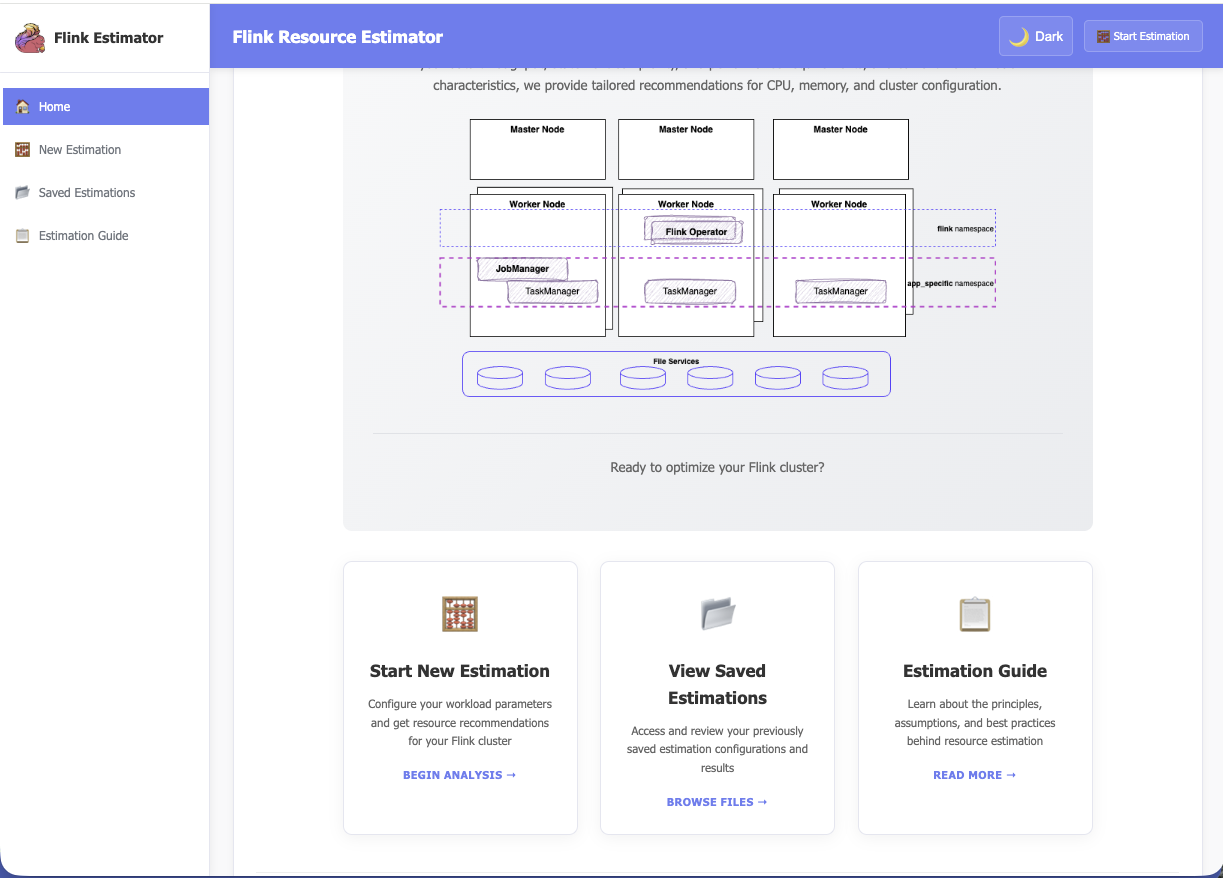
I tentatively built a flink-estimator webapp with backend estimator for Apache Flink or Confluent Platform Cluster sizing.
The tool needs to be simple, it limits the number of parameters, and persists the estimation as json on the local disk to be able to save different estimations or update existing ones.
To access this web app there is a docker image at dockerhub - flink-estimator, or cloning the repository and run with python.
- use
docker-compose up -dOR run with:./run.sh - Access via web browser http://localhost:8002/
1.1 Bring up new cluster/environment.
Context
Use this recipe when you need a new Flink environment (e.g., dev / stage / prod or a new region) backed by one of:
- Confluent Cloud environment
- A Kubernetes cluster (new or existing).
- CP Flink components installed via Helm (Flink K8s Operator + CMF).
- An existing Kafka cluster (Confluent Platform or Confluent Cloud).
Out of scope: deep infrastructure provisioning automation. The focus on the Flink layer once K8s and Kafka exist.
The Components to install for each deployment approach:
In the context of a Confluent Platform deployment, the components to install are represented in the following figure from bottom to higher layer:

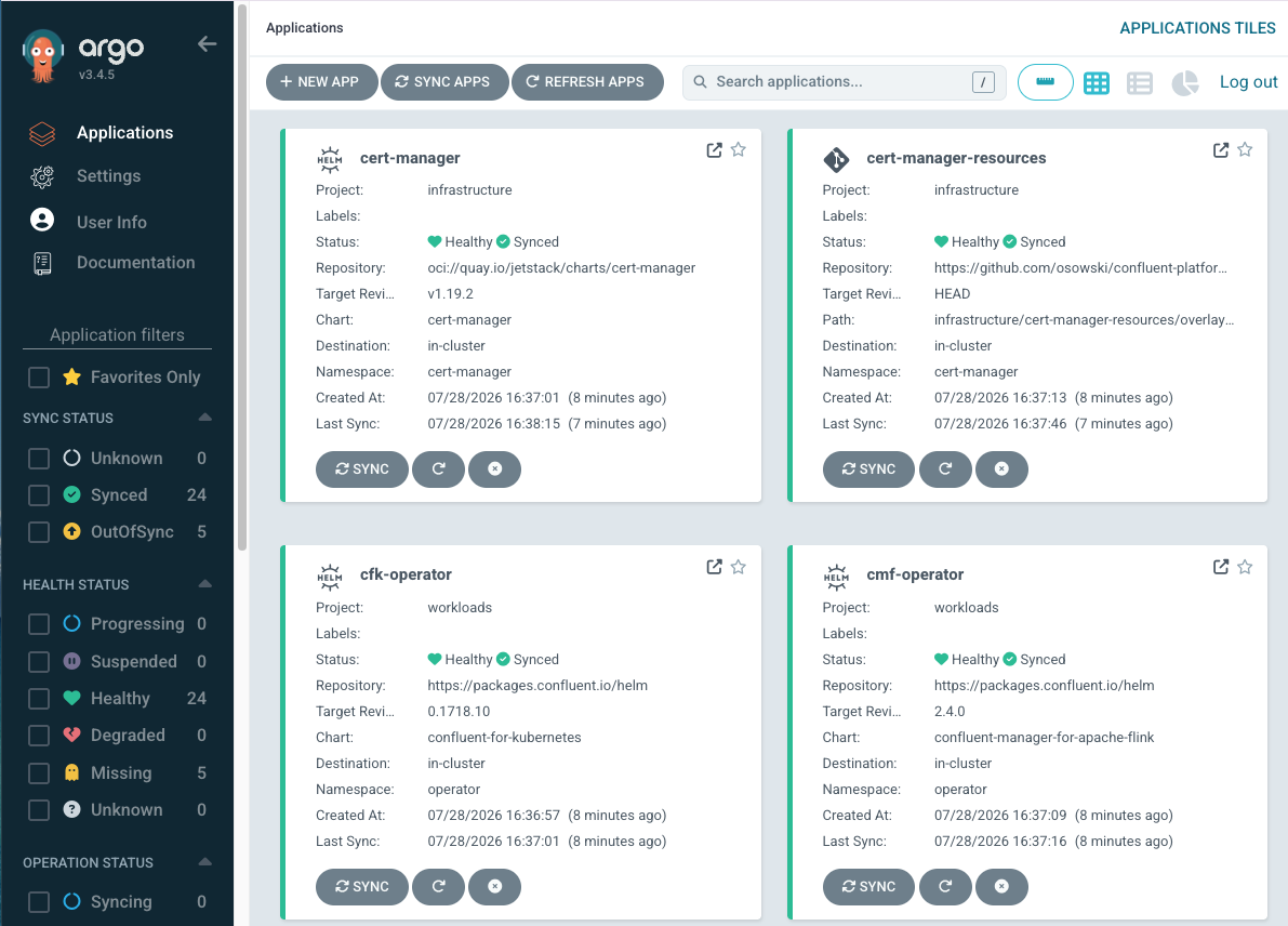
See a pure gitops deployment using ArgoCD.
For an equivalent open source the components are:

Confluent Cloud is a serverless SaaS. The deployment includes the following components, deployable via infrastructure as code:
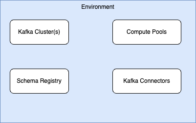
See this deployment based on git and terraform
Preconditions / Checklist
- kubectl, helm, confluent CLI, yq,
- Sizing / T-shirt: from Project estimator: Rough T-shirt size for CMF, operator, JobManagers, TaskManagers (CPU, memory) based on expected jobs and throughput.
- Information about Kafka bootstrap endpoints, and schema registry URL
- Durable Storage for State: Object store or filesystem accessible from all K8s nodes (e.g., S3/GCS/minio, HDFS) for checkpoints/savepoints.
- ENV_NAME (e.g., development, staging, prod)
- K8S_NAMESPACE_CMF (e.g., cpf), K8S_NAMESPACE_FLINK (e.g., flink), CMF_HELM_VERSION (e.g., ~2.1.0), FKO_HELM_VERSION (e.g., ~1.130.0),
- CHECKPOINT_URI (e.g., s3://my-bucket/flink/checkpoints/), SAVEPOINT_URI (optional, e.g., s3://my-bucket/flink/savepoints/)
- terraform, confluent CLI
- Organization ID, Confluent Cloud API key and secrets scoped as Cloud resource management.
- get CONFLUENT_CLOUD_REST_ENDPOINT
- If reusing an existing Kafka Cluster, get KAFKA_API_KEY, KAFKA_API_SECRET, KAFKA_CLUSTER_ID
Procedure
We list here the high level steps. For dedicated chapter on Kubernetes deployment
- Prepare Kubernetes Namespaces
- Install Flink Kubernetes Operator (FKO)
- Install Confluent Manager for Apache Flink (CMF) - Not need for pure Apache Flink
- Configure Durable Storage for State
- Expose CMF API for Environment Management
- Create a Flink Environment (Logical Environment)
- Smoke-Test with an Example Application See a pure gitops deployment, see getting started or EKS deployment
With Terraform (see deo environment definitions): 1. Set variables TF_VAR_confluent_cloud_api_key and TF_VAR_confluent_cloud_api_secret 1. Run the terraform init then terraform plan to finally deploy the resources terraform apply --auto-approve
Gotchas
- Durable storage is not optional in production; losing it, it means losing consistent recovery
- For multi-namespace or multi-cluster topology, leverage CMF’s multi-cluster support
- Adopting a declarative configuration for all applications and infrastructure components deployed to Kubernetes clusters with ArgoCD: see Rick Osowski's repository addressing a GitOps practices for Confluent Platform deployment running on Kubernetes.
1.2 Adjust cluster resources (more TaskManagers, more slots).
Context
Use this when a Flink job or compute pool is under-provisioned: sustained backpressure, growing Kafka lag, or repeated "NoRecentCheckpoints"/resource exhaustion alerts or when on Confluent Cloud the statement becomes Degraded.
Confluent Platform for Flink or Apache Flink:
When you need to increase or decrease the cluster’s capacity by adding/removing TaskManagers, or by changing taskmanager.numberOfTaskSlots (slots per TM).
This recipe is primarily cluster/platform facing; job-level parallelism tuning is covered in a separate “Scale a Flink Job” recipe.
Always try to clarify the goal:
- Reduce backpressure / lag.
- Accommodate larger state (checkpoints/savepoints, RocksDB state) or Statement State becoming too big.
- Support more concurrent jobs/statements in a shared pool.
Preconditions / Checklist
- Have a good understanding of the performance situation with observability stack like Grafana dasboards and other metrics
- Get a clear assessment of the current number of Task managers and task slots per task manager
- Confirm current job parallelism and utilization
- Revisit current traffic pattern, versus the one used for platform sizing
Inputs / Parameters
- Current compute pool limits
- Current number of jobs per compute pool
Procedure
- Diagnose whether you need more TMs, more Slots, or both. Check TM utilization and slot usage:
- Are TaskManagers at or near 100% busy?
- Are all slots occupied? Are there idle slots but backpressure at specific operators?
- Check compute-pool / CFU limits (CP Flink / CCFlink): Ensure your target TM count/size stays within declared the limit; large TMs and more slots affect costs.
-
Adjust TaskManager count for horizontal scaling - (CP and OSS).
- Adjust max CFU per compute pool, add more compute pool in Confluent Cloud. TM count is controlled indirectly via compute pool CFU and Autopilot/DSA; horizontal scaling is typically automatic.
- For operator-only K8s Flink, TM count commonly set via deployment/Helm values for the TaskManager deployment (e.g., replicas in K8s or CFK spec).
-
Monitor - Check that:
- Backpressure decreases.
- Checkpoint durations stabilize or drop (CP or OSS).
- TM CPU/memory are in a reasonable range (no massive under-utilization).
-
(Optional) Scale down later (CP or OSS): Once load drops, you can scale TMs down again to save resources. In CCFlink Autopilot will handle this automatically.
- Adjust Slots Per TaskManager (Vertical Slot Scaling). Change
taskmanager.numberOfTaskSlotsto alter concurrency per TM. Get at least one core per busy slot for non-trivial jobs.
Understand slot semantics
Each TaskManager is a JVM process; each slot is a fixed share of that TM’s resources. More slots per TM = more tasks sharing CPU, heap, network and disk; good for many small jobs, risky for heavy jobs.
Update slot configuration. In a FlinkApplication / K8s spec (CP Flink example):
Changing taskmanager.numberOfTaskSlots typically requires restarting TaskManagers
Watch for increased GC pressure and longer checkpoint times. Assess disk I/O saturation (RocksDB state, shuffle).
Rollback
If the change makes things worse (more instability, timeouts, cost spikes):
- Revert TM Count / Slots
- If jobs fail or degrade: Temporarily move the most critical jobs to a separate, known-good pool / cluster with conservative settings. Then investigate per-job parallelism / skew, the RocksDB / disk hot spots, the autoscaler behavior.
- Document Effective Settings
2- Upgrading Flink Components
This section applies only to self managed Flink deployments. As Confluent Cloud is a managed service, the product version to version update is transparent to the users.
2.1 Upgrade Flink minor/patch versions.
Context
Preconditions / Checklist
Inputs / Parameters
Procedure
Rollback
Gotchas
2.2 Rolling upgrades and compatibility considerations.
Context
Preconditions / Checklist
Inputs / Parameters
Procedure
Rollback
Gotchas
3 Disaster Recovery & Multi-Region Strategies
Disaster recovery is about business continuity. Review the core principles of DR in this note. The figure below, simply presents the important metrics to consider and impact on data loss and service recovery.
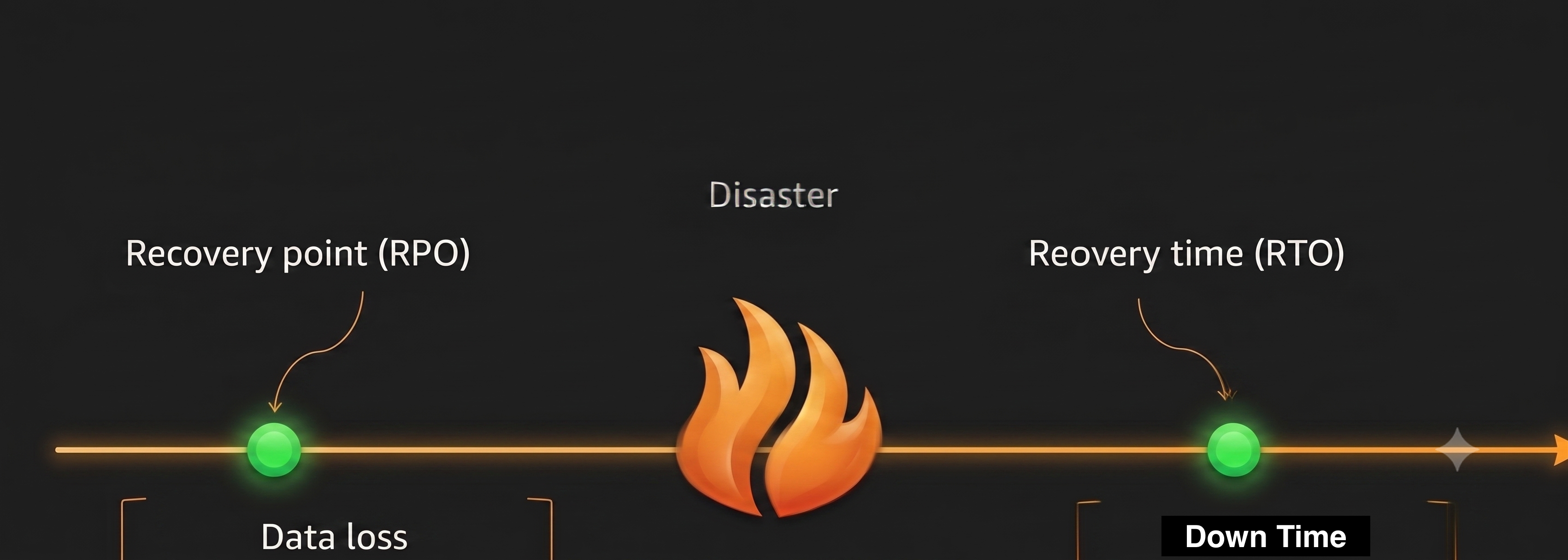
DR for Flink depends on the deployment model (Confluent Cloud, Confluent Platform, or open-source) and always requires a DR strategy for Kafka and Schema Registry first. Data Stream Processing is not Multi-Region Cluster, it uses separate clusters with asynchronous replication/Cluster Linking instead of one stretched, synchronously replicated MRC cluster. MRC is generally used for high availability and near-zero data loss across multiple site, but only Kafka may support it.
Data and schema replication (exact replication including offsets and schemas) are prerequisites; Flink state recovery builds on that.
Resiliency
Resiliency is the ability of a workload to recover from infrastructure or service disruptions, dynamically acquire computing resources to meet demand, and mitigate disruptions, such as misconfigurations or transient network issues. It is important to adopt a resilience-by-design mindset directly into software architecture. It addresses DR (restore service) and Availability (prevent loss of service).
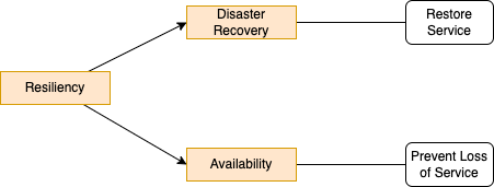
Apply the sharing responsibility of resiliency: cloud provider for resiliency of the cloud: infrastructure. Customer responsible for resiliency in the cloud: adopting instance deployment across multiple locations, support self-healing, design for resilience.
It is important to bridge the gap between software and infrastructure by designing resilience directly into the application layer, by using architecture patterns, modern enterprise capabilities, and governance to bring end-to-end coherence and integration across applications, platforms, and data pipelines.
With agentic systems deployment, it should be possible to have autonomous, intelligent agents to handle unpredictable variables in real time.
- Cloud Providers are offering multiple regions for disaster recovery, and multiple availability zones within a region for high-availability. They do not communicate on how the physical allocation is done between physical data centers. But it is possible that an availability zone is a data center building in other part of the city, with fiber optical links. This means Kafka cluster in multi availabiltiy zones can support some DR requirements. Cloud within a region, DR may be acceptable, but in general DR considerations are for region failover to mitigate regional outages: earthquakes, electrical disaster...
- If availabilty zones is sufficient to support disaster management, it is the most cost effective solution as a lot of services, like Kafka, support synchronous replications between AZs (See Confluent resilience documentation). Always clarify those topologies with the cloud provider.
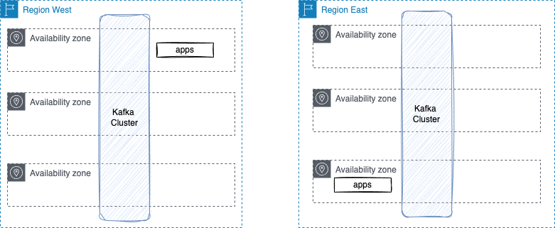
- Failure to one Cloud Provider's AZ should be easily recoverable, and are well managed by software like Kafka, Flink, kubernetes...
- In recent data center disasters, most of the failure were linked to networking configuration issues, cutting the access to control plane: it is always difficult to take the decision to failover in this case. Recent wars are also showing a data center can be a target to bombing, and failover region may be in other countries.
In this recipe we consider region failover.
3.0 Assessing resiliency needs
-
Start by looking at business impacts:
- assess cost of downtime?
- business metrics used to measure impact? and any existing metrics and tools to compute outage impact.
- 70% of CIO wants to be resilient, 80% have nothing in place, and most has no real metrics.
-
Assess what is the current method to detect downtime, and the definition of downtime. Moving to a standby region cost time and effort, getting a clear assessment of what downtime means is very important before triggering the failover. Is it latency? is it missing orders? Is it network split?
-
Get an application inventory by category of criticality, including compliance requirements.
-
What is the process in place to alert human for downtime?
- What are the current observability practices to clearly identify disaster?
- What is the current recovery strategy? When companies are asking ISV to support some DR requirements, it should never be in a vaccum, but part of bigger initiative. I recall spending 3 hours on technical meeting on how to support DR for our software and discovering that the DR site was another room in the same building as the primary site...
As any flink solution, the following need to be deeply assessed:
-
What Flink application and SQL statements to consider in scope of DR? Map applications, flink pipelines with their expected RPO and RTO. When building analytics data products, most likely those metrics can be relaxed. Here is a simple template:
Data product Flink Pipeline DML Consumers RTO RPO c360 analytics dml.c360-fact-cust.sql BI dashboard 4 hours 20 mn -
Can Flink's state be recreated? This is driven by the underlying Kafka Clusters RPO and the retention policies.
- How long is tolerable to recreate that state? This is driven by the overall RTO.
- What is the semantic expected by consumer applications? This is driven by consuming app tolerance. Semantics options are: exactly-once, at-least once (duplicate possible), at-most once (data loss and duplicate possible).
- Is the Flink job processing deterministic? will a Flink job always output the same results?
3.1 Strategies for DR
- Backup/restore is for lower priority workload, cost less, and provision cloud resources after the event. RTO/RPO in hours.
- Pilot Light: Data is live but services are idle. Provision some resource and scale after event. RPO/RTO in 10s of minutes.
- Warm standby: The DR site is always running but smaller scale. Resources will scale after the event. RPO/RTO at the minutes level.
- Multi-site active/active: Zero downtime, near zero data loss. This is really for mission critical services.
For Flink we can consider two main patterns:
- Active/active: Two (or more) regions run identical Flink jobs continuously, both processing the same input (with replication delay in the secondary). Best for low RTO, large state, or when you need exactly-once semantics and both regions to produce the same results.
- Active/passive: Flink runs only in the primary region. In the DR region, Flink jobs are started at failover time. Best when state can be recreated quickly (e.g. stateless or small time windows) or when at-least-once/at-most-once is acceptable. It is relevant for use cases that fail forward, and that require failing back to the original region within weeks of the outage. Stateful/windowed Flink statements may still be deployed in this mode, but those statements need to be running against mirrored source topics, allowing Flink to maintain equivalent state with the primary region. Do not mirror any flink sink topics because asynchronous replication can leave state inconsistent and duplicates.
We are going to detail those patterns.
3.2 DSP Elements to consider
Recall a traditional data streaming processing includes at least the following components:

The following view presents the deployed components, which we should assess how, each component, needs to support DR:
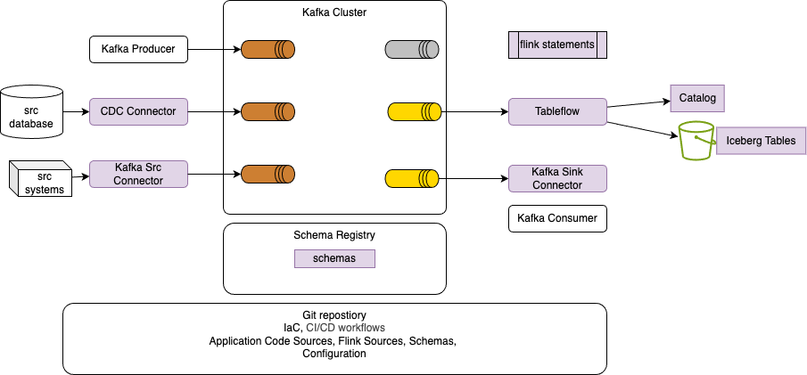
| DSP Components | DR Considerations |
|---|---|
| Kafka Topics | Data replications and offset integrity. RPO zero is not achievable with asynchronous replication. |
| Schemas | Same versions on both sides, schemaId integrity |
| Kafka source connectors | Configurations for both sites |
| Kafka sink connectors | Configurations for both sites |
| Flink applications/statements | Same Version deployment, state construction, offsets propagation |
| Tableflow | Configuration for both sites, triggered by code, resume from replicated storage |
| Catalog | |
| Iceberg Tables | Replicatd by cloud provider service- 15 minutes latency is common. |
Tableflow specific
As of now, 09/2026, Tableflow is regional, and does not replicate the table state to other region, so recovery means reconstructing each table in a second region, fomr the Kafka Topics. When those topics were created by Flink processing, this is not an issue as Flink has to run in parallel to keep its state and respect normal operation expected RTO.
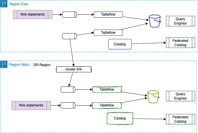
In case the topics are cluster linked (with schema IDs preserved via schema linking), just enabling Tableflow on those. If Tableflow is not active, starting it on DR after failover, may lead to bigger RTO as, it needs to reprocess the lag. Larger tables recover slower.
Be sure to set the primary topics to infinite retention before any failover, so the full changelog is retained, replicated to DR region, and each table can be rematerialized from offset 0. This could be relaxed if the business requirements authorize it. Also compacted topics have discarded history.
The DR buckets need to be configured upfront. The external catalog needs to federate to the DR Tableflow catalog. As the catalog namespace is linked to the kafka cluster, those names are different for each region. Also bucket names and folder path will be different than from primary site.
Downstream consumers need to point to new tables.
The above materialization mechanism can be set active/passive or active/active with duplicate records and the need to reconcile at the Iceberg tables query engine level.
Obviously all other components of the figure above needs to have DR runbooks too.
When looking at the Flink architecture, it is important to recall that Flink relies on low-latency inter-node communication (TaskManagers exchanging shuffle data via RPCs) and tight state coordination, running one cluster across regions creates severe network bottlenecks and split-brain risks. Most of modern flink deployments are done as FlinkApplication on top of an orchestrator like kubernetes, the worker nodes host those applications, and application is job manager and n task manager. Flink Kubernetes Operator acts as a control plane to manage the application deployment life cycle.
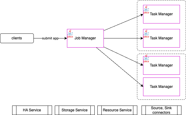
Instead, multi-region resiliency requires deploying independent, fully self-contained Flink clusters in each region, paired with a cross-region streaming data pipeline. Also the source and sink connector selections impact the design of Flink DR solution. Using Kafka or Iceberg connectors have very different impacts.
The following figures illustrate what elements need to be considered for disaster recovery for the different platforms:
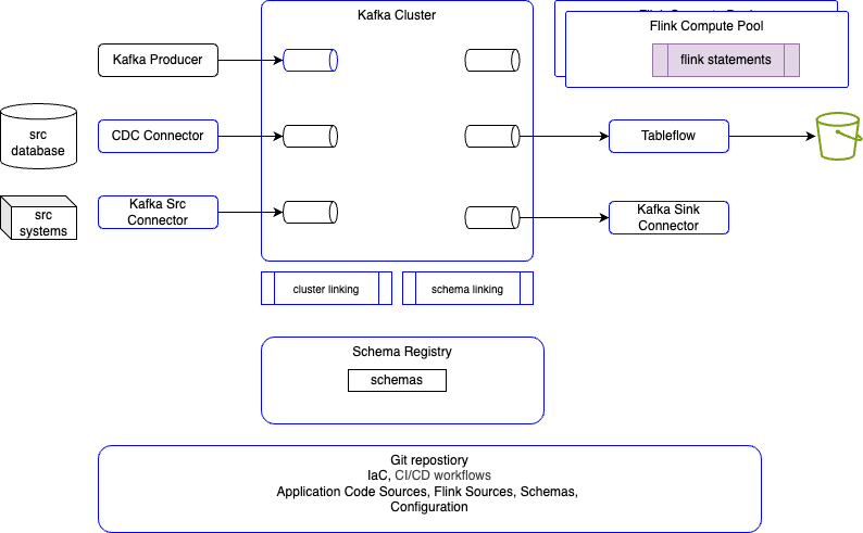
- The blue color border means, those elements can be configured as infrastructure as code (e.g. terraform).
- Confluent Cloud control plane and data planes are separate points of failures. Data plane can run in any supported Cloud provider's regions.
- Communication between Control plane and data planes is done with the 'mothership' kafka cluster.
- TBC
- The blue color border means, those elements can be configured as code.
- Need to decide which elements can run and being created in the DR site.
-
Active means, clients applications write data to the primary cluster. Passive, DR site, captures the replicated data and schemas. Active/active, clients write to either cluster.
-
How networking hostname and CIDRs are defined in both sites.
- Flink Statements are most of the time stateful, and run continuously. Rebuild state cost RTO. A Flink statement stopped and restarted is the same as starting a new job. Assess if sources topics have extactly the same records.
- In case of active/passive, failover decision is triggered by human but automated by scripts and runbooks. Clients must bootstrap to the DR cluster once a failover is triggered.
- Disaster means source site is not reachable.
- Assess if the consumer apps of records generated by Flink statements are idempotent and accept duplicates (the most recent consumer offsets may not have been committed to the destination cluster when a disaster occurs). Also consumers and producers must be tolerant of some RPO: there may be a small number of messages that have not been replicated to the DR cluster at the time of failover.
- Not all kafka topics need to be replicated to DR sites. For Flink pipelines, it may be relevant to replicate only the source topics.
3.3 Networking
Recalls that:
- VPC runs in a specific region. They can be connected via VPC peering to do inter-region traffic.
- Security policies control ingress and egress traffic to/from VPC
- Kafka use a binary protocol (not HTTP based). It use TLS with the common protocol of SASL_SSL for both authentication and encryption. Kafka Client applications cannot access Kafka through a traditional load balancer.
- Client apps need DNS and port # of bootstrap servers advertised listener address. They need a network path to Confluent Cloud network

- Confluent Cloud requires TLS for encryption for all communication. It also requires authentication using API_key and secret
- Assess if public endpoint is an option to access Kafka, schema registry...
- Revisit ingress to private network from Confluent Cloud network. Managed connectors are going to access your data sources and data sinks, your data sources and data sinks need to be accessible over the internet or via VPC gateways / private links.
- VPC to Confluent Cloud can be interconnected using Private Link, which helps to access CCloud via private endpoint within VPC. Private Link network regroups an endpoint service, and n endpoints in the VPC or VNet associated with the endpoint service. Those endpoint service establishes connectivity to the Kafka cluster; each endpoint is an IP address that lives in one of the VPC subnets. This is a unidirectional connection, nothing in Confluent Cloud can access private environment. On the VPC side, SRE need to set up wildcard DNS records to forward all traffic destined for Confluent brokers to the correct Private Link endpoint that exists in the VPC. On-premises network can access CC via VPC. See those notes.
-
Access to Schema Registry - which is metadata only - is only accessible over the Internet
-
Cluster Linking is set as bidirectional mode to enable topic data and metadata to sync between two clusters and should be used in all disaster recovery patterns. In the event of a disaster, a bidirectional Cluster Link can reverse the direction of data and metadata to support easy failover and/or fail back.
Cluster Link
Cluster Links on Confluent Cloud enables data replication between two kafka clusters. Can be created with Terraform, cli or REST API. Cluster links are created on the destination Kafka cluster. Source cluster may also be a Confluent Platform or Apache Kafka cluster.
By default, a cluster link is a one-way bridge but can be set to be bi-directional. Kafka clusters need to be dedicated or enterprise. A Service account is the principal to process the cluster link, and needs api key/secrets on both clusters. ACLs need to be set so read from topics on source cluster.
Cell Architecture
Modern cloud Native solution adopt the cell architecture, as replacement of the traditional model of a single, multi-AZ cluster with multiple independent, single-AZ clusters. This model treats the Availability Zone as a strict fault domain. Each cell represents a fully functioning, independent replica of the application infrastructure.
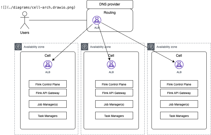
It is not necessary to map cell to AZ, it is even recommended to have cell over multi-AZs too, within a VPC.
It looks Confluent Cloud is based on such cell architecture. For example Flink endpoints are separated from cloud.confluent.io/environment. The high level view of this architecture may look like:
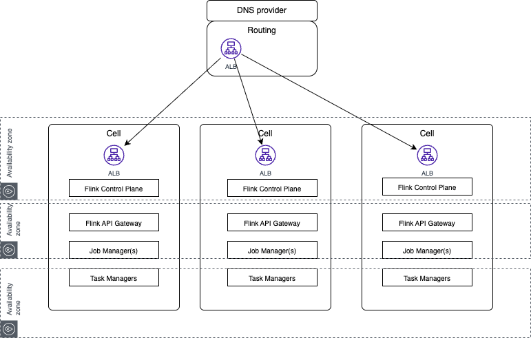
To address routing to cell, we need to setup dedicated ALB per cell with cross-zone routing disabled. This routing layer may include application load balancing, meaning specific tenant's traffic can be routed within a specific cell. Intra-service traffic is contained inside the cell boundary. Chatty microservices that exchange high volumes of data within a cluster generate zero inter-AZ data transfer charges because all pods run within the same AZ.
Microservices inside a cell communicate solely with other pods inside the same cell, maintaining static stability. Data persistence services remain centralized and multi-AZ.
The values are:
- Lower blast radius
- Higher Mean Time Between Failure (MTBF)
- Lower Mean Time to Recovery (MTTR)
- Safer deployment (which enforces strong GitOps automation).
See AWS cell-based microservice architectuyre on AWS - Video
Resources
3.4 Active-passive pattern
Context
Use this when you need to survive a full region or data-center failure. Flink DR options assume Kafka and Schema Registry DR first: exact replication of data (including consumer offsets) and schemas.
Flink jobs are started, in second region, only on failover.
This approach is best for stateless jobs, or when states can be created quickly: Flink Jobs Window Size and time to recompute job state < RTO. Also for solutions based on at-least once, or at-most-once. Even for stateless jobs, exactly-once semantics is not supported as duplicates are possible at the Flink pipeline sink.
On Confluent Cloud, Cluster Linking and Schema Linking deliver topic and schema replications.
On Confluent Platform or self-managed Flink, you replicate topics (and offsets) and schemas by your own means (e.g. MirrorMaker, cluster links, or shared storage).
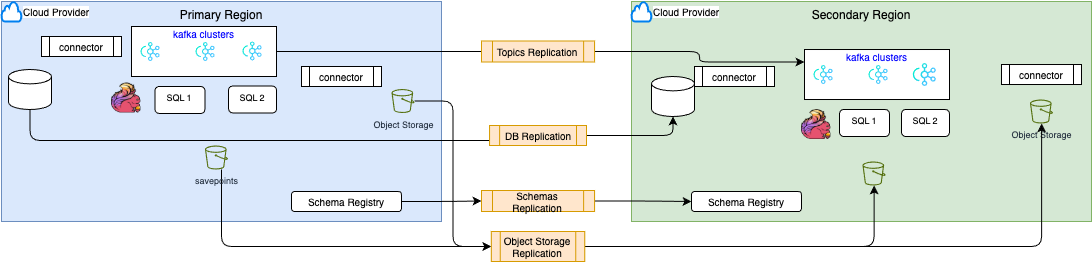
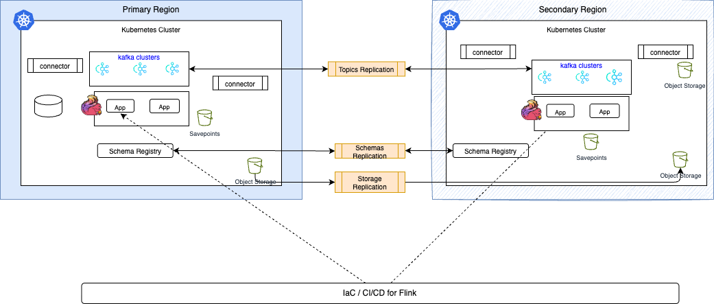
A generic a ctive/passice DR component views will reley on the selected platform:
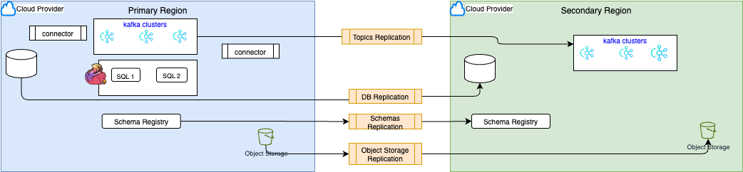
- DB Replication is for transactional payload and leverage RDBMS replication mechanisms
- Topic replication is supported by Confluent cluster link
- Schema replication is for Confluent Schema linking
- Object Storage replication is a Cloud Provider service
- Flink Compute pools are created by IaC and can be created upfront in both regions
- Cluster Linking creates “mirror topics” with globally consistent offsets. Messages on the source topics are mirrored identically onto the destination cluster, at the same partitions and offsets.
- Each Confluent Cloud environment is allowed one Schema Registry instance, which is used by all of the Kafka clusters, Connect clusters, Flink statements. Schema linking replicates schemas (and schema id) between schema registries. It requires the destination’s Schema Registry2 to be in IMPORT mode, which allows new schemas to be written only by Schema Linking.
For Confluent Platform or Apache Flink on Kubernetes the replications includes resource definitions, configurations, savepoints replications. It is easier to test and practice DR by moving producers and consumers to the DR cluster and reversing the direction of data and metadata. 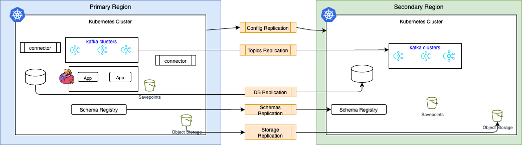
- DB Replication is for transactional payload and leverage RDBMS replication mechanisms
- Topic replication is supported by Confluent cluster link
- Schema replication is for Confluent Schema linking
- K8S configuration, ETCD config.. need to be replicated
- Storage softwware may have their replication capabilities to manage cross-region replications.
Preconditions / Checklist
- Provision API keys for the DR cluster in advance and store them in a vault for low RTO.
- Kafka and Schema Registry DR are in place: topics and consumer offsets replicated to the secondary cluster; schemas replicated (e.g. Schema Linking on Confluent Cloud). see Cluster Linking DR and Failover
- Cluster Linking is asynchronous: RPO is bounded by mirror lag while RTO depends on client failover and time to start Flink and restore state, which may take hours.
- Topic retention in DR must exceed the time needed to rebuild state (e.g. window size or TTL). Without enough retention, results will be wrong, or only subset of queries would work. To avoid duplicates of Flink table content, do not replicate Flink created topics.
- Use event time (not processing time) for windows and aggregations so replay produces correct results.
- Create the appropriate role bindings in the DR environment for applications and users that will failover.
- Assess if cluster links need to be set bi-directional to easily failback to primary, once failed over.
Inputs / Parameters
| Parameters | Description |
|---|---|
| Primary / DR cluster bootstrap, API keys | Stored in service discovery / vault for fast client switch on failover. |
| Kafka Cluster Linking config (Confluent Cloud) | This is a direct connection between source and destination clusters. Consumer partition-offset sync, ACL sync, mirror topics (or auto-create), optional filters. |
| Schema Linking | To replicate schemas between Registries. It replicates the schema ID for data consistency. The schema replication is always active/passive as the destination registry is in import mode only. |
| Flink state recreation window | Max window/TTL and retention must allow full replay. |
| Semantics | Exactly-once (active-active with deterministic jobs), at-least-once, or at-most-once (affects duplicate handling and restore guarantees). |
Procedure
- Keep Flink job definitions in version control for automation. Do not run Flink in DR during normal operation.
- On failover: Create/start Flink statements in DR (from specific offsets if available, or from earliest offset so states are rebuilt from replicated input).
- Switch Kafka consumers to the DR cluster
Monitoring
- Monitor mirror lag (Confluent Cloud Metrics API, Console, or REST) to bound RPO.
Rollback
- After primary region recovery: decide whether to fail back (switch clients and optionally Flink back to primary) or keep running in DR. If failing back, replicate any new data produced in DR back to primary (e.g. bidirectional cluster link) and then switch clients and Flink back to primary.
Schema Management
- When disaster failover happens, Flink can keep reading schema-based data only if schemas have already been replicated to the DR region’s Schema Registry via Schema Linking. Otherwise record deserialization will fail.
- In the standard DR pattern, primary SR stays READWRITE, secondary SR stays IMPORT, and during failover you must reverse the schema link. See product documentation.
- On failover, ensure Schema Link is caught up, then promote/switch Kafka side.
- If you need Flink to run CREATE TABLE after failover, the DR side must allow schema writes to the active SR and the user/service account must have the required SR/Kafka permissions
3.5 Active-active pattern
In the scope of classical web applciation, active/active really means that a user will loose connection to a site and be routed to another site in milliseconds: session data as cookies may be recovered. For Kafka, producer and consumer may use a bootstrap list of URLs including both sites. For Flink the query/job deployments is done on both site in parallel. The main problem is to assess what to replicate, and if the Flink pipelines need to be consumed or not.
The biggest challenge is to avoid data collision in the same data store: entity created in two regions in less than 100ms can collide when replicated. So replications need to be done on data that could not be sourced on both sites.
The approach is to have two identical Flink jobs or pipelines of jobs run in parallel continuously in both regions. They process the same data, with some replication delay in the secondary region.
This is recommended for low RTO requirements, with Flink jobs with large states, or solutions requiring Exactly-Once semantics, or when it is critical that the 2 regions have exactly the same data results.
Procedure
- Replicate only input topics to the DR region (e.g. cluster link from primary to DR). Do not replicate Flink output topics into the other region’s input to avoid duplicates.
- Replicate schema from Primary to secondary.
- Deploy the same Flink statements/jobs in both regions, reading from the local Kafka cluster (primary or DR copy). Ensure queries are deterministic and support out-of-order arrival.
- Mirror configuration: same service accounts, RBAC, private networking, and table/job definitions in both regions.
- On regional failure: direct clients (producers/consumers) to the DR cluster (bootstrap and credentials via service discovery/vault); Flink in DR is already running.
TBC
3.6 Apache Flink / CP backup/restore of state backend
Context
Use this when you need to back up Flink job state for recovery, upgrades, or migration, or when designing for regional failure (disaster recovery). Flink state is captured via checkpoints (automatic, lightweight, Flink-managed) and savepoints (manual, portable, user-managed).
- Checkpoints: Provide automatic recovery from job failures. Flink creates, owns, and may delete them. Stored in state-backend–specific (native) format; optimized for fast restore. In production, store checkpoints in durable, shared storage (e.g. S3, GCS, HDFS, MinIO) so that JobManagers and TaskManagers can recover after process or node failure.
- Savepoints: User-triggered, consistent images of job state for planned operations (version upgrades, graph changes, rescaling). Stored in canonical (backend-independent) or native format; not deleted by Flink. Required when you need to restore a job in another region or after a major change.
By deployment:
- Confluent Cloud: Regional, multi-AZ service. Checkpoints run every minute for in-region fault tolerance. No user-configurable state backend; state is managed by the service. In a region loss, there is no built-in cross-region state restore—you must implement a cross-region DR strategy (see 3.2 below).
- Confluent Platform (CMF) / Kubernetes: Checkpoints and savepoints go to object or distributed storage (e.g. S3, HDFS). CMF supports Savepoint resources (trigger, list, detach, start from savepoint) via REST API. For failover between data centers, durable storage must be accessible from both (or replicated); Kafka topics (and offsets) must be replicated; then Flink applications can be restarted from checkpoints/savepoints in the DR site.
- Open-source Flink (e.g. K8s operator): Same concepts; configure
state.checkpoints.dirand optionalstate.savepoints.dirto durable storage. Use Kubernetes HA withhigh-availability.storageDirfor JobManager metadata.
Preconditions / Checklist
- Durable, shared storage for checkpoints (and savepoints) that all Flink processes can access (e.g. S3 bucket, HDFS, GCS, MinIO). For cross-DC DR, storage must be reachable from the DR site or replicated.
- Checkpointing enabled in the job (and optionally configured retention).
- For savepoints: job is running (or you have an existing savepoint path to adopt/import).
- For Confluent Cloud: no direct state-backend configuration; ensure Kafka + Schema Registry DR (e.g. Cluster Linking, Schema Linking) before designing Flink DR.
Inputs / Parameters
| Parameter | Description |
|---|---|
state.checkpoints.dir | Directory for checkpoints (e.g. s3://bucket/flink/checkpoints/). |
state.savepoints.dir | Optional directory for savepoints. |
execution.checkpointing.interval | Checkpoint interval (e.g. 1 min). |
execution.checkpointing.externalized-checkpoint-retention | RETAIN_ON_CANCELLATION or DELETE_ON_CANCELLATION. |
| Savepoint path | For restore: path returned when creating a savepoint, or CMF savepoint name/UID. |
Procedure
Backup (savepoint) — Confluent Platform / CMF
- Trigger a savepoint via CMF API (applications or statements):
POST /cmf/api/v1/environments/{env}/applications/{appName}/savepointsor.../statements/{stmtName}/savepoints- Optional body:
spec.path,spec.formatType(e.g.CANONICAL),spec.backoffLimit.
- Poll or watch savepoint status until
status.stateisCOMPLETED; usestatus.pathas the restore path. - Optionally detach the savepoint (applications only) to preserve it after deleting the application:
POST .../savepoints/{savepointName}/detach. For external/open-source savepoints, register as detached:POST /cmf/api/v1/detached-savepointswithspec.path.
Backup (checkpoint) — self-managed (CP/OSS)
- Ensure
state.checkpoints.dirpoints to durable storage (e.g. enable checkpointing to S3). - Let Flink create checkpoints at the configured interval. Optionally set
execution.checkpointing.externalized-checkpoint-retentionto retain checkpoints on cancel. - For a consistent “backup” suitable for migration or DR, trigger a savepoint (as above) rather than relying only on the last checkpoint.
Restore
- From savepoint: Start the application with
startFromSavepointset to the savepoint path, CMF savepoint name, or UID. In CMF: create/update application withsavepointName/uid/initialSavepointPath, orPOST .../applications/{appName}/start?startFromSavepointUid={uid}. - From checkpoint (automatic): After a failure, Flink (and K8s HA if configured) restarts the job and restores from the latest successful checkpoint when no savepoint is specified.
- Confluent Cloud: Failed statements auto-restart using the last checkpoint; there is no user-visible backup/restore of state to another region—use active-active or active-passive (see 3.2).
Rollback
- If a restore from savepoint fails or the job misbehaves: stop the job, fix code or state compatibility, then start again from an earlier savepoint or from scratch (no savepoint).
- If you restored with wrong parallelism or backend: take a new savepoint, adjust config, and restore from that savepoint (canonical savepoints support state backend change and rescaling; see Flink checkpoints vs savepoints).
Gotchas
- Checkpoints are often incremental and backend-specific; savepoints in canonical format are portable and support state backend change and rescaling. Native savepoints are faster but have limitations (e.g. no state backend change).
- You cannot create a canonical savepoint for a job with an operator using
enableAsyncState()(CMF/Flink). - Deleting an attached savepoint in CMF requires the Flink cluster to be running; use
force=trueonly when necessary (can leave orphaned data in blob storage). - Confluent Cloud does not expose state backend or checkpoint/savepoint paths; DR is achieved by running Flink in the DR region against replicated Kafka/Schema Registry and accepting state rebuild or active-active/active-passive design.